
Introduction
The “Bubble Dancer” RES glider is essentially a big brother of the Allegro-Lite, with a 120" span and 1000 in^2 wing area. The idea was to combine the composite Allegro’s layout, some new thin airfoils, and a bit of off-the-shelf carbon. The object was to make a big first-class thermalling ship which could also tolerate wind and strong winching and that anyone could build. The target category was the increasingly popular RES class. Blaine Rawdon and Bill Watson also took part in the design, and the Allegro-Lite wood wing 2m glider was a prototype for this glider.
The design was optimized for ease of construction , resulting in a rather unique glider. At about 31 oz (880 gr) , it has a very low sink rate – about 0.8 ft/s. A very big 2" x 36" spoiler gives good landing control like on the AL, and it can be seen thermalling very often from hand tosses.


Fuselage Pod
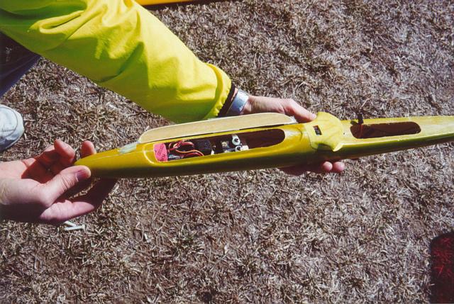
Fuselage pod showing servo installation and radio gear, along with Wing saddle, spoiler extension and switch.
Wing
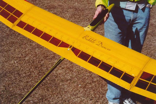
A view of the center section of the wing, with the spoiler closed.
Spoiler
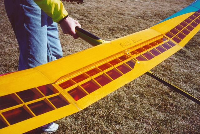
Spoiler open.
Tail and V-Mount
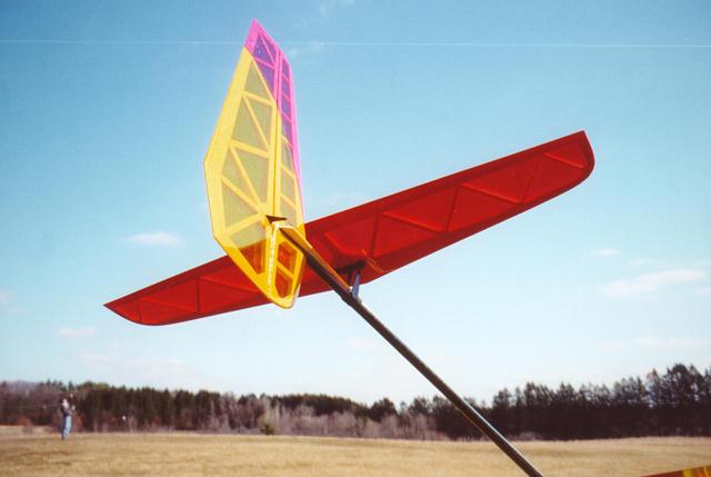
Vertical tail and Horizontal all moving tail mounted on its V-mount.
Bubble Dancer Airfoils
| Airfoil | Coordinates | CompuFoil COR files | Polars |
|---|---|---|---|
| ag35 | ag35.dat - 4 KB | AG35.COR - 4 KB | ag35_polars.pdf - 31 KB |
| ag36 | ag36.dat - 4 KB | AG36.COR - 4 KB | ag36_polars.pdf - 25 KB |
| ag37 | ag37.dat - 4 KB | AG37.COR - 4 KB | ag37_polars.pdf - 30 KB |
| ag38 | ag38.dat - 4 KB | AG38.COR - 4 KB | ag38_polars.pdf - 24 KB |
| ht21 | ht21.dat - 3 KB | Horizontal and vertical tails |
Drawings and Construction Notes
- Bubble Dancer Plans files/bd_V3.pdf - 26 KB files/bd_V3.dxf - 639 KB
- Wing Plan files/wing_plan_V2b.pdf - 26 KB files/wing_plan_V2b.dxf - 536 KB
- Spar Layup files/spar_V2.pdf - 10 KB
- Joiner files/joiner_V2.pdf - 11 KB
- Joiner Construction files/joiner_build.pdf - 3 KB
- Making Kevlar Tubes for Joiners
- Fuselage Plan files/fusepod.pdf - 49 KB files/fusepod.dxf - 253 KB
- Horizontal Tail Plan files/htail_V2.pdf - 15 KB files/htail_V2.dxf - 140 KB
- Vertical Tail Plan files/vtail_V2.pdf - 14 KB files/vtail_V2.dxf - 154 KB
- V-mount Plan files/bd_vmount.pdf - 20 KB files/bd_vmount.dxf - 408 KB
Extras
- Big Wing Plan files/big_wing_plan.pdf - 21 KB files/big_wing_plan.dxf - 24 KB
- Stick Dancer files/dancer_fig.pdf - 5 KB files/dancer_fig.dxf - 79 KB
- Bill of Materials - 4 KB
Rib Sets for Laser Cutting
The DWG files here contain rib, web, and LE sanding template patterns for laser cutting. All patterns have been adjusted to allow for a 12 mil laser kerf.
| Description | DWG | |
|---|---|---|
| Panel-break ribs | files/ribs/brk_ribs.pdf - 6 KB | files/ribs/break_rib.dwg - 32 KB |
| Center panel ribs | files/ribs/cen_ribs.pdf - 7 KB | files/ribs/cen_rib.dwg - 58 KB |
| Center panel shaping templates | files/ribs/cen_temp.pdf - 8 KB | files/ribs/cen_web.dwg - 8 KB |
| Mid panel ribs | files/ribs/mid_ribs.pdf - 9 KB | files/ribs/mid_rib.dwg - 81 KB |
| Mid panel shaping templates | files/ribs/mid_temp.pdf - 8 KB | files/ribs/mid_web.dwg - 9 KB |
| Tip panel ribs | files/ribs/tip_ribs.pdf - 8 KB | files/ribs/tip_rib.dwg - 71 KB |
| Tip panel shaping templates | files/ribs/tip_temp.pdf - 8 KB | |
| Tip panel webs | files/ribs/tip_web.dwg - 8 KB |
Photos


[Courtesy of Mark Drela, Jan 2005 - Photos courtesy of Jeff Newcum]