MAKING MINI-SOCKETS (COUPLERS) FOR HLG, TAIL PIECES, ETC. (11/10/98) by Harley Michaelis, LSF 023
As raw material to work with, Dubro makes a nylon socket head 10-32 x 2" “Wing Bolt” (4 in a package). Micro-Fasteners (see ads in mags) carries an inexpensive 50 count package of 10-32 x 2" “Nylon Socket Head Cap Screws”. Cut 1" or so long to work with. Round alum. rod (1/4", etc.) can also be used if a lathe is available. The sketch below, about 2 X in size, illustrates what a mini-socket might look like fashioned out of these.

The larger end can be opened as needed to fit around the output gear with a little clearance for splining with epoxy. Typically for tiniest micro-servos, this means a hole around 3/16" in diameter and 1/8" deep.
If a lathe is available, open the larger hole first. Then reverse the piece to make the small hole. Preferably, keep the bottom closed to prevent epoxy from getting into the smaller hole when splining ,as it is critical to keep it free of epoxy for good CA bond. Size it to leave a little clearance with the intended drive shaft so thin CA can be thoroughly wicked between hole and shaft. Reduce bulk and weight by turning the outside down to a minimum.
If a drill press is being used, thread the bolt into a hole in a board. Center to open the socket end , then make the smaller hole, using the dimple left by the larger bit as a centering guide. When splining, place a tiny piece of masking tape inside to keep epoxy out of the small hole.
When finalizing the sockets to length, leave 3/8" to 1/2" of the skinny part to assure ample surfaces in contact for good CA bond. Be sure the thin CA is fresh and allow several hours to cure well in the closed environment.
If the case has a molded-in ring around the output gear, and if the larger opening in the socket is sized to just fit around or inside the ring, it is easy to center it when splining. When length is finalized, make a small notch or slit in the skinny end to facilitate wicking CA glue around the shaft. Be sure to score up the shaft for good bond.
TAIL PIECE APPLICATIONS: The advent of ever-smaller/lighter micro servos and use of the Rotary Driver System with mini-sockets makes it more practical to mount servos in tail pieces. This avoids the use of horns, clevises, springy and odd-shaped pushrods, cables and associated drag and slop in these assemblies, too.
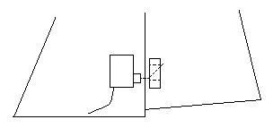
Think of the sketch below as part of a fin/rudder, or one side of a stab/elevator or V-tail assembly. Center-mounting of servo, pocket and hinges would seem the simplest way to go. Mounting the servo squared to the hingeline is shown, but if it is positioned at 45 degrees, the bent end of the shaft would point straight back, allowing use of smaller pocket openings. The pocket must still snugly fit the shaft to avoid flutter and allow for a little lateral movement, so a tube in the moving surface is not suited to the application.

Similar installation procedures would apply as for ailerons, although the “bearing” at the hingeline could be nothing more than a CA or epoxy-reinforced hole. You could first wax up a piece of rod slightly larger than the intended shaft, insert, apply glue, cure, twist to break the bond and remove the rod. An access hole would be needed in the side of the fin, etc., through which to drop CA glue when bonding the real shaft to the coupler.