COUPLER IDEAS FOR THE ROTARY DRIVER SYSTEM by Harley Michaelis, LSF 023

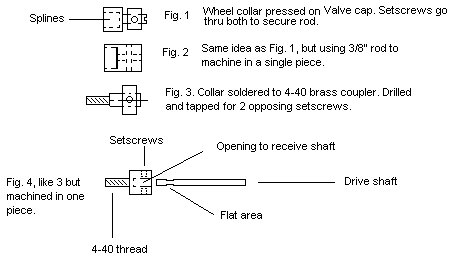
Fig. 1 involves using the Tru-Flate valve cap item 47-103, splining it after seating a 5/32" brass Dubro wheel collar on it. Drilled out 11/64", the collar goes on with a press fit. The assembly is then drilled and tapped across for two 6-32 setscrews. The cap is okay for a 3/32" drive shaft. Drill that hole with a #41 bit, so there is a little clearance to also wick CA glue between rod and hole. The combo is very strong. See details under RADS/RFDS about splining in a valve cap. However, with a collar on, the 3/32" wire used to center the splines can be positioned with a setscrew, rather than CA glue.
Fig. 2 shows how the coupler could be machined as a one-piece item with a lathe, out of tempered aluminum rod, etc. It could be sized to take a larger rod, such as 1/8" for heavy duty applications. You could drill across to put in even 4 setscrews. 6-32 is suggested as there is a ball ended hex tool to fit the opening and really bear down on them. The wimpy little wrenches provided with a collar tend to readily slip and not seat the screws well.
Another thought is to make the Figure 2 item out of nylon, as follows: Locate a 3/8" nylon bolt that has a smooth unthreaded section under the head or find some other round plastic rod. Remove the head to have a squared-off, flat end. Get hold of a brass output gear that matches that of the servo being used. Mount it on the end of a threaded rod as a handle and set up a jig to center the gear in the nylon. Heat the gear with a torch so it can be pressed in the nylon to form a fitted spline. This would provide great strength for critical installations.
Splining allows the coupler to be slipped off the gear and rotated to easily secure more than one setscrew on the rod, then be slipped back on in neutral position. There is no significant force tending to pull the coupler off the gear. Once its position is finalized, drill a 1/32" hole through coupler and gear and secure it with an ordinary pin, cut to 3/8" or so. A dab of white glue will hold it and is easy to remove if necessary.
Fig 3. involves tapping the output gear to receive a shortened threaded coupler, such as a 4-40 size, which receives a 3/32" rod. The same collar as in Fig. 1 could be used, soldered on the coupler. Not shown, a lock nut or lock washer could be jammed against the output gear and help prevent the coupler from slipping inside the gear. This setup, unlike a splined one, requires some consideration of how to get to the setscrews to tighten them. The amount the servo could be rotated might not allow access to the opposing setscrew. However, if there is access, the coupler could be unscrewed a little to do so and then be reseated on the lockwasher.
If a lathe is available, this could be made as a one-piece item, as illustrated in Fig. 4. The opening could be sized as desired, even for a 1/8" shaft.
As to rods, stainless steel is really nice, as it readily takes a low radius bend and won’t rust. The bend can be made in a vise by inserting an end in the jaws, then pounding close to the jaws with a hammer. If a 1/8" shaft is used, it’s big enough to file some flat spots in parallel planes, to seat the screws on to prevent turning and also retain the rod.